|
In This Issue:
|
| Introduction to Induction |
|
|
|
|
|
|
|
|
|
|
|
|
|
|
|
|
|
|
|
|
|
| Greetings to our Atomic 4 customers, and welcome to our Winter/Spring 2017 email newsletter. We have compiled the following information that we hope you find helpful. For a complete listing of our Atomic 4 parts & services, you may visit www.moyermarine.com or call Ken at our phone parts line, 610-421-4436. |
INTRODUCTION TO INDUCTION |
I’m a lousy cook; not because I’m unable to read the lines in a cookbook and accurately measure out the necessary ingredients, but because I have almost no understanding of the myriad ways in which the more subtle flavors of various foods, spices, and herbs interact with each other to create a really great meal. In a similar fashion, I sense that many of you who call our tech service line for assistance in working though some issue with your ignition system have no problem reading the lines in some troubleshooting guide. You call because you don’t have a good functional understanding of how the various elements of the induction process interact to create a really great secondary discharge.
At its root, induction is a rather simple process that takes place between a pair of circuits that (although close to each other) are not physically connected in any way except that they share a common ground. But there’s a “spooky” part. One of the two circuits within an “inductive relationship” is able to somehow reach across the air space between the two circuits and build up a small voltage which causes a current to flow within the other circuit.
So as not to set our learning bar too high, the process of induction, including the whole notion of DC current behaving as a flow of electrons along conductors, jumping across air spaces, and mostly at the speed of light is described by most experts as “theory”, which means that even they can’t deal with some of these spookier parts. In other words, we do not need a nuclear physicist’s understanding of the induction process, but we do need a good functional understanding of how it works so we can recognize and manage its effects.
AN EXAMPLE OF INDUCTION FROM “THE GREATEST GENERATION”: Induction usually occurs as the result of purposeful design, but it can also occur accidentally. I’d like to share an actual example of unplanned induction that was used in a training course for Aircraft Accident Investigating Officers that I attended in the mid-1960s. The Electrical Engineering instructor used an old accident report from the 1940s to introduce the concept which resonated with me to the degree that I was able to develop at least a good layman’s (functional) understanding of the process. I hope it will do the same for you. |
|
|
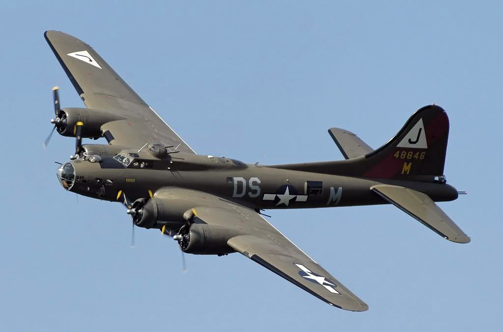
During the Second World War, a B-17 was returning to its home base in England after a night bombing raid over Germany. Part of the raid was aborted due to bad weather over the target area, and the crew was bringing part of their bomb load home. The sun was just coming up as the plane crossed back over the coast of England when, suddenly, all of the remaining bombs fell from the plane. Fortunately, the bombs fell on a mostly deserted coastline and no one was hurt.
In the ensuing investigation, the Bombardier was the first crew member to come under scrutiny as causing the accidental release. However, the Bombardier had an iron clad alibi. He happened to be in the head at the other end of the plane when the bombs left their racks.
The investigation was actually getting nowhere until the Accident Board asked every crew member to write down exactly what they were doing at the precise time the bombs were dropped. From this list of crew actions it was noted that the Copilot had just turned the navigation lights to the OFF position.
In following up on this lead, it was discovered that every time the nav light switch on this particular B-17 was turned ON and then back OFF, the small relay that supplied power to the bomb release mechanism activated, but only when the switch was turned to OFF.
It was subsequently discovered that the tail light on this particular B-17 had been reported as being defective on the previous mission. In repairing the defective tail light circuit, the crew chief (to save time) had simply installed a new wire to the tail light, spiraling it along the outside of the same wiring bundle that contained the circuit to the small bomb release relay. This wiring bundle ran almost the entire 75 foot length of the plane.
A Consulting Electrical Engineer assigned to assist the Accident Board concluded that sufficient electrical energy was induced from the newly installed temporary tail light circuit into the bomb release circuit to activate the small bomb release relay each time the nav lights were turned OFF.
As the report went on to explain, each time the nav light switch was turned to the ON position, an electromagnetic field propagated out from the temporary tail light wire installed by the crew chief. As this invisible electromagnetic field swept across the circuit to the bomb release relay, a small charge was induced for a split-second into the bomb release circuit. However, this induced voltage was not strong enough to activate the bomb release relay. But, when the nav light switch was subsequently turned to OFF, the retreating electromagnetic field swept across the bomb release circuit even faster than it did when the nav light switch was turned ON, and this time the induced charge in the bomb release circuit had sufficient strength to activate the small bomb release relay and the bombs were released.
CONNECTING THE DOTS BETWEEN THE B-17 AND YOUR ATOMIC 4: Here are a few observations on the induction process as it played out in the B-17 that should help you to relate it to the ignition system in your Atomic 4:
The actual induction process took place within the length of the wiring bundle where the tail light and bomb release circuits ran in close proximity to each other. The tail light wire served as the primary circuit, which in your ignition system would be the primary windings inside the coil. The wire leading to the small bomb release relay became the secondary circuit which, of course, are the secondary windings within the coil. The nav light switch functioned as the breaker points or electronic ignition (EI) module outside of the induction zone to open and close the primary circuit.
It’s important to notice that induction only occurred at two very brief times on the B-17; once when the electromagnetic field swished out across the bomb release circuit when the nav light switch was turned on, and again when the nav light switch was turned OFF and the electromagnetic field swished across the bomb release circuit again as it retreated back into the tail light circuit.
It’s also critically important to recognize that the retreating of the electromagnetic field back into the tail light circuit induced a much larger voltage within the bomb release circuit when the nav light switch was turned OFF than it did when the field propagated out from the tail light circuit when the nav light switch was first turned ON. For those of you who are prone to ask why; the only explanation I ever heard that makes any sense to explain this difference in speed between the propagation and retreating of the electromagnetic field has to do with the fact that it’s made up of energized “subatomic particles” and when you try to move them around at the speed of light, they obey at least some of the same mass laws (including) the role of inertia as other matter does. In short, it’s apparently more difficult to move these little rascals out from their “resting place” in the primary circuit when it's energized than it is to “let them fall back” into the conductor when the circuit is de-energized. |
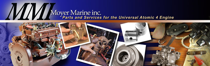
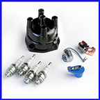
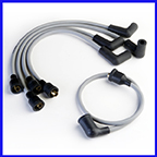
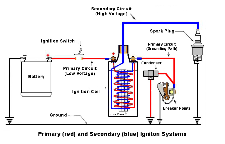
| ON TO THE ATOMIC 4 IGNITION SYSTEM: As you study the following very basic schematic of an ignition system that exists in an Atomic 4, remember that most of the primary circuit exists outside of the coil itself, and it’s quite lengthy on most boats. It begins at the big battery terminal on the starter solenoid, runs through the ignition switch (usually in the cockpit), then back to the positive terminal on the coil, then through the primary windings within the coil, and it finally reaches ground through the breaker points (or EI module) and the housing of the distributor. Is it any wonder that most ignition problems develop within the primary circuit? Much of the secondary circuit also lives outside of the coil but it is limited to the coil wire, distributor cap, rotor, plug wires and plugs. |
|
SUPERCHARGING THE BASIC DESIGN: It requires much more energy to cause an arc to jump across a ½” air space (in the neighborhood of 20,000 volts) than to activate the coil of the small bomb release relay. The following additional enhancements are therefore necessary to greatly boost the secondary voltage so as to be useful in our ignition systems:
Both the primary and secondary circuits inside the coil are configured into thousands of wraps (hence the name “coil”). In an actual coil, the primary wraps are physically large enough so that the secondary coil can fit inside of the primary windings.
Wrapping the primary circuit into many coils has the effect of shaping and consolidating the electromagnetic field which greatly increases its strength and its ability to induce a higher voltage in the secondary windings.
The individual wraps within the secondary coil are said to have a “multiplying effect” which increases the induced voltage even higher by the time the charge gets to the discharge post at the top of the coil. It’s my understanding that the multiplying effect works like a “series” relationship between each of the thousands of windings in the secondary coil - much like the 1.5 volt batteries multiply by 5 in a five-cell flashlight to produce 7.5 volts. Imagine the small voltage induced into each winding within the secondary coil as being multiplied by thousands of wraps.
Notice that in the schematic, a soft iron core (easily magnetized) is installed down through the center of the primary and secondary windings. The purpose of the iron core is to further consolidate and strengthen the electromagnetic field to induce an even higher voltage in the secondary circuit.
As a final enhancement, a condenser is added across the breaker points in conventional systems to reduce the amount of sparking as the points open and close. The strongest electromagnetic field is created around the primary windings of the coil when the primary circuit is opened very abruptly. As long as arcing continues between the contacts of the breaker points as they start to open, a small current will still be flowing through them until they get apart far enough to stop arcing, thereby slowing down the opening of the primary circuit. Picture the duration of the arcing between the points as being what happens to a light bulb in your home when turning a dimmer switch all the way from bright to off instead of using a toggle switch. The condenser gets rid of the “dimmer switch effect” caused by the arcing between the breaker points so that the points can open the primary circuit instantly and cause a stronger electromagnetic field (more like the functioning of an Electronic Ignition module).
THE BIG FINALE: You can demonstrate the induction process and perform a quick functional check of your coil at the same time by using the following steps. For those of you self proclaimed visual learners, we refer you to our video tech tip, "Operational check of a coil".
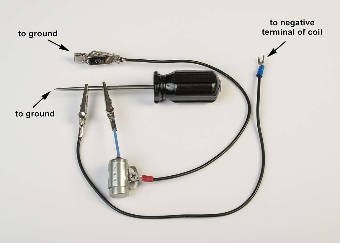
(1) Remove the black wire from the negative terminal of the coil and replace it with a short length of wire (any short scrap of 12 or 14 gauge will do). The wire only needs to be long enough to reach from the negative terminal on the coil to a spot on the head so the wire can be used to intermittently ground and unground the negative terminal of the coil. If you clip the end of the wire to an ice pick you’ll be able to make and break the contact to ground very cleanly.
(2) Prepare a second grounding wire to connect between the ice pick and ground, through a condenser (as per the following photo).

When you get to step 4, the condenser will provide an alternative path to ground as you make and break the circuit to ground with the ice pick and make the secondary discharge from the coil lead much stronger.
(3) Remove all wires from the positive terminal of the coil and install a jumper wire between it and the big battery cable on the starter solenoid.
Caution: When connected, this jumper wire functions exactly the same as turning on the ignition switch, so it should only be connected during the time you’re actually using the coil to create a secondary discharge during this demonstration.
(4) Remove the coil lead from the center of the distributor cap, and with the jumper wire connected to the positive terminal of the coil, hold the coil lead with your left hand so that the tip is about ¼” from the head. Then take the ice pick with your right hand and alternately make and break contact with the head.
Each time you remove the ice pick from contact with the head, a secondary discharge should jump from the end of the coil lead to the head. The length to which you’re able to stretch the secondary arc is the best indicator of its strength. A good ignition system will create at least ½” to ¾” of arc.
DESIRED LEARNING OUTCOMES: The Air Force was persistent in establishing Desired Learning Outcomes (DLOs) for their training programs to insure that the educational goals of the courses were met. I thought that since we borrowed from their accident files, we should consider several DLOs for this newsletter:
1) With the points or EI module closed, be able to trace your entire primary ignition circuit from the large battery terminal on the starter solenoid to the final grounding point. Hint, the final part of the grounding path extends through the breaker plate and the housing of the distributor, so be sure to check all those points of contact for corrosion.
2) Be able to trace your entire secondary circuit.
3) Be able to manually create a secondary discharge from the end of your coil lead to the cylinder head using the temporary leads described in the previous section.
4) The next time you watch the movie “Memphis Belle”, imagine yourself in the copilot seat of a B-17 when the pilot frantically calls out; “Hey gang, we’re approaching the drop zone a bit early, where in the “H” is the Bombardier?” Would you (a) run around looking for the Bombardier, or (b) calmly hit the intercom button and say; “No sweat Captain, I saw how the crew chief rewired the tail light circuit last night, so I can initiate the bomb run from here”.
We hope that you will have as much fun with this newsletter as we did preparing it. You may have noticed that we purposefully avoided the matter of timing and distributing the secondary discharge to the appropriate cylinders. We did this so that we could focus 100% on the basic concept of induction. You can refer to our video tech tip "Ignition timing" to help you sort through any timing issues you may have. |
|