In This Issue:

Sudden Shutdowns
Spring Maintenance
Ignition Protection
Suggested Tools
Greetings to our Atomic 4 customers, and welcome to our February2014 email newsletter. We have compiled the following information that we hope you find helpful. For a complete listing of our Atomic 4 parts & services, you may visit www.moyermarine.com or call Ken at our phone parts line, 610-421-4436.

SUDDEN AND UNEXPECTED SHUTDOWNS

Throughout the almost thirty years that MMI has been in existence, there have been frequent requests for “cookbook” style troubleshooting checklists.  I’ve personally resisted this approach, believing that it’s far better to understand the technical underpinning of why certain things happen – or don’t happen – than to mindlessly follow a sequence of steps that seldom exactly fit the situation with which you’re confronted.
I’m now back peddling on that historic position in one specific scenario; troubleshooting unexpected and sudden engine shutdowns on open water (see pages 2 and 3).  This change of heart is in recognition of the fact that if your engine stops while you’re clawing your way around the proverbial rocky lea shore in 30 knots of wind, you’re probably not going to be in the best position to reflect calmly on whether the engine stopped as though someone accidently turned the ignition switch off (hard shutdown), or as if you ran out of fuel (usually a softer shutdown).  Nor are you likely to be in the best state of mind to reflect on all maintenance that was performed since the engine last ran OK (still a very good starting point in calmer circumstances), or on the myriad troubleshooting suggestions located in our Community Forum. 
Before getting to the guide itself, here are a few preliminary general steps you can take to save critical time in emergency conditions:

  • Prepare a quick response kit to use in case of an unexpected shutdown, using the thirteen (13) items indicated throughout the guide with red asterisks as a starting point.
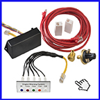
  • Install an emergency backup electric fuel pump in series with the primary fuel pump, controlled with a manual switch mounted in some convenient location.  In function, this pump falls somewhere between a primary fuel pump which requires an Oil Pressure Safety Switch (OPSS), and a tank to tank transfer pump which does not.  If connected directly to the switched ignition circuit, this pump (with the mere flip of a switch) can be used to deal with at least 4 common fuel system issues which are otherwise extremely difficult to remediate while under way; (1) primary fuel pump failure, (2) blown fuse, (3) an OPSS failure, and (4) if your primary pump is still working and your problem is a partially blocked fuel line, the backup pump will double the head capacity of your primary pump and hopefully provide enough muscle to keep the engine running until you can get to a safe harbor.  CAUTION:  When using a backup fuel pump, check the lines, filters, and valves of the fuel supply system frequently for leaks, especially if the primary fuel pump is a mechanical pump.  If at any time a fuel leak is discovered, it’s best to set an anchor and shut the engine off until the source of the leak can be remediated.         
  •  Immediately before casting off, brief your crew on who should take the helm if you have to go below, and (because you may not be able to fix everything) review procedures on how to set an anchor and call for a tow if necessary.

The 13 steps in the guide are a combination of diagnostic and corrective actions which begin with a quick check for spark, and then move through either the ignition or fuel system as appropriate.  As a general principal, we try to lead you to the most likely causes and/or the easiest to perform items early in the guide, ending up with the more difficult possibilities and those with decreasing likelihood of success.  You should never have to accomplish more than half of the 13 steps before your engine springs to life; or you know that there is no reasonable “on the water” fix.  In those cases, suggestions are provided at key points within the guide directing you to sail to a safe harbor, or set an anchor and call for a tow. 
All checks and remedial items in the guide have had a relatively high likelihood of success in dealing with a sudden and unexpected shutdown based on historical precedence.  Therefore, you won’t find things like a total loss of compression, loss of oil pressure, overheating, catastrophic mechanical breakdown, etc included in the guide. 
We hope you will avail yourself of the pedagogical benefit of the guide by reviewing each of the steps in the following guide while in your slip with a cup of coffee in your hand, rather than waiting until some dark and stormy night to search for the various items on your engine, or for tools and spare parts referenced in the guide.  

TROUBLESHOOTING AFTER AN UNEXPECTED SHUTDOWN:
A “cookbook” approach to restarting an engine after an unexpected shutdown

STEP 1 - Close the raw water through-hull valve, and reopen it only after the engine starts.
STEP 2- Remove the coil lead from the distributor cap and hold it approximately ¼” from the cylinder head as the helmsman tries to restart the engine. A *remote starter button can be used to run the starter if single-handing. If you do NOT see a normal secondary discharge from the coil lead, continue to STEP 3. If you DO see a normal secondary arc (at least 1/2”), go directly to STEP 7 (the beginning of fuel system checks).
STEP 3 - Install a *jumper wire between the positive terminal on the coil and the big battery cable on the starter solenoid. The jumper wire should be12 or 14 gauge, 3 feet in length, with a large alligator clip on one end and a small clip on the other.
STEP 4 – Try to start the engine. If the engine starts, keep the jumper wire installed and treat it as you would an auxiliary ignition switch; connecting it only to run the engine, and disconnecting it to shut off the engine. If the engine will not start with the jumper wire installed, remove the jumper wire and continue to STEP 5.
STEP 5 - Install a *12 volt test light between the primary terminals on the coil. If the test light turns on and off as attempts are made to start the engine (indicating a normal condition), go to STEP 6. If the test light does not illuminate or remains on continuously, clean the contacts of the points with a piece of cardboard (conventional ignition), or replace the EI module (electronic ignition systems). If the test light now turns on and off, ignition should be restored. If the engine still won’t start, go to STEP 6.
STEP 6 - Replace the *coil. If you do not have a spare coil, remove the old coil from its mounting bracket and suspend it away from the engine block using a nonconductive cord. If the coil was short circuiting to the block, moving it a few inches away from the block will sometimes enable it to work long enough to get to a safe harbor. If there is still no secondary arc from the coil, sail to a safe harbor, or set an anchor and arrange for a tow.
STEP 7 - Remove the fuel fill cap from fuel tank. If engine starts, let the fill cap off and proceed to a safe harbor. If the engine will still not start, continue to STEP 8.
STEP 8 – Tap the side of the carburetor with a small hand tool while trying to start the engine. If the engine starts, proceed to a safe harbor and then burnish the seat of the float valve with a bluntly pointed *3/16” wooden dowel. If engine still does not start, proceed to STEP 9.
STEP 9 - Activate the emergency backup *electric fuel pump. If the engine starts, proceed to a safe harbor. CAUTION: When using a backup fuel pump, check the lines, filters, and valves of the fuel supply system frequently for leaks, especially if the primary fuel pump is a mechanical pump. If at any time a fuel leak is discovered, it’s best to set an anchor and shut the engine off until the source of the leak can be remediated. If there is no backup fuel pump installed, continue to STEP 10.
STEP 10 – Check the fuse in the electric fuel pump circuit. If the fuse is blown, replace it with a *10 amp fuse and proceed to a safe harbor. If the fuse is not blown, continue to STEP 11.
STEP 11 – Install a jumper wire between the fuel pump side of the oil pressure safety switch and the positive terminal of the coil (essentially by-passing the OPSS). If the pump is still not heard to be clicking, or engine will still not start, remove the jumper wire and continue to STEP 12.
STEP 12 – Remove the ½” hex-headed main passageway plug from the bottom of the float chamber and allow the fuel to drain into a clean glass jar. Check for water or other contaminants and operate the fuel pump catching the fuel in the glass jar until the fuel is clean. Replace the main passage plug and try to start the engine. If the engine will still not start, continue to STEP 13.
STEP 13 – (Last desperate attempt) separate the fuel line at several locations between the pump and the fuel tank and blow back toward the tank to clear any restriction. Use a *three-foot length of fuel line and appropriate fittings to bring the end of the hose to a place where you can blow back into the tank to clear the line. If the fuel supply lines cannot be opened, or the engine will still not start, sail to a safe harbor, or set an anchor and arrange for a tow.


Spring Commissioning
This is the time of year many of us have been longing for. The time when approximately half of the 20,000 Atomic 4s estimated to be in active service will emerge from a winter lay-up. After spring commissioning, these engines will once again become vehicles of re-creation for their owners. As you might expect, we at MMI also look to this season as a time of renewal and try to make every spring a positive experience for our customers. Here are four simple checks which history has taught us will pay the biggest dividends for the time spent during this very busy time.


Pre-start checks: (all accomplished with the raw water through-hull closed):

1) OIL: Check oil and replace as necessary.

2) COMPRESSION: Remove all spark plugs and hold your thumb over each spark plug hole while turning the engine over a couple seconds. As long as compression is sufficient to force past your thumb no matter how hard you press, the compression is OK (80 psi or above). If any of the valves show signs of sticking (noticeably poorer compression), a few squirts of Marvel Mystery Oil will usually help those cylinders back to life.

3) IGNITION: While plugs are removed, check them for condition and replace them if they have carbon deposits (especially if the carbon is oily). If you have conventional ignition (points, condenser, rotor), rub a small piece of match book cover between the points to clean them. Then remove the coil lead from the center of the distributor cap and hold it 1/4” from the head or block while turning the engine over. Check for a strong secondary arc which can be stretched to at least 3/8”. Note: linked products above are for late model motors, see early model section for corresponding parts.

4) FUEL: With clean filters (primary and secondary), carefully remove the main passage plug or bowl drain from the carburetor and pump enough fuel through the system and into a clean glass jar to insure perfectly clean fuel. Reinstall the main passage plug or bowl drain and pump for an additional 5 or 10 seconds to re-prime the carburetor. The priming lever on mechanical pumps can be used in this step.

Electric fuel pumps will need to have a jumper wire installed across the oil safety switch so the pump will run by turning on the ignition switch. In electric fuel pump systems, it's very convenient to install a second electric pump upstream from the primary filter with a manual switch to use in this step. The second pump can also serve as an emergency back-up in case the primary fuel pump fails.

NOTE: One of the more useful side effects of 10% ethanol fuel is that it dissolves varnish build-up within older fuel systems. If you discover orange colored crud moving through your fuel system, repeat the above step and be prepared to check and replace filters several times during the season. In most cases, varnish build-up will be completely removed after several additional filter changes.

For the first start of the season, we recommend keeping the raw water through-hull valve closed until the engine starts in order to avoid any possibility of water flowing back into the exhaust manifold should the engine prove to be a bit hard starting. In fact, if you know that your particular exhaust system is problematic in terms of allowing water to flow back into the exhaust manifold, it makes sense to follow this suggestion permanently.

Hoping the 2012 season will be the best ever for you and your sailing companions,

Don Moyer


SUGGESTED SPARE PARTS AND TOOLS FOR CRUISING
 
The following items should only be considered as a starting point in devising a list of spare parts and tools. Please add or subtract from the list as appropriate in meeting your specific needs. Remember; your best assurance against being caught in a threatening situation (or working your way out of one), depends not only on the spare parts that you might have on board, but on a thorough understanding of the different systems in your engine. 
 
SPARE PARTS:
 
1) Coil.
 
2) Four new spark plugs.
 
3) Spare fuel pump.
 
4) Spare water pump (a spare impeller may suffice if no snap ring is required, and the pump is less than 5 seasons old, or has less than 500 operating hours).
 
5) Three or four feet of engine water hose, fuel line (with appropriate sized hose clamps), and a small roll of electrical wire (12 or 14 gauge).
 
6) A roll of good quality electrical tape.
 
7) Spare filter elements for any filters you have on board.
 
8) Spare fuses.
 
9) Alternator belt
 
10) Spare alternator (optional).
 
RECOMMENDED TOOLS (In addition to "normal hand tools"). Be sure to add any tools that would be needed to install any spare parts that you might add to the above list.
 
1) A small digital volt/ohm meter.
 
2) A three-foot length of 14 gauge wire with a ring terminal on one end, and a clip on the other.  This wire can be used to "hot wire" the ignition system in the event of a failure of the primary circuit within the boat's electrical system.
 
3) Electrical crimping tool and a small supply of ring terminals, butt splices, etc.
 
4) Remote starter switch (available for about $30 at most auto parts stores).
 
5) A 12 volt light with alligator clips to use for checking continuity.
 
6) MMI Service and Overhaul Manual


IGNITION PROTECTION

If you bought a new Atomic 4 engine from Universal in late 1978, the starter, alternator, and distributor would have been Ignition Protected. Nineteen seventy-eight was the year the US Coast Guard required that all spark producing electrical components on marine engines be Ignition Protected in accordance with SAE J1171.

WHAT IT MEANS FOR SPARK PRODUCING COMPONENTS TO BE IGNITION PROTECTED:
The underlying concept of Ignition Protection is based on the assumption that if an engine compartment fills with an explosive atmosphere, the explosive mixture will, in due time, permeate the interior of any spark producing component on the engine (examples include starter, distributor, alternators, etc.).
It is also assumed that once an explosive mixture enters a spark producing component, an explosion will occur within the component during the normal course of starting and operating the engine. The goal of Ignition Protection therefore, is to control an explosion, should one occur, inside a spark producing component so that it will not ignite the explosive atmosphere within the engine compartment itself.

HOW IGNITION PROTECTION IS DESIGNED INTO A COMPONENT:
The principle challenge in designing an electrical component (or modifying one) to be Ignition Protected is to provide enough built-in “leakage” from the interior of the component to release the heat and pressure of an explosion from within the component fast enough to prevent the component from being blown apart by the explosion, but slowly enough (through one or a number of tiny openings) so that the escaping combustion gasses cool below the ignition point before reaching the explosive atmosphere within the engine compartment.
Some electrical spark producing components already have close to the necessary amount of leakage from their interiors to pass the test for ignition protection and require only a modest modification. On other spark producing components, like Delco starters manufactured prior to 1978, the challenge is much greater.
In modifying Delco starters to be Ignition Protected, a steel disk is installed between the motor and nose cone with a brass bushing around the shaft of the armature. This disk, along with a few other minor modifications, slows the escaping gasses during an explosion within the starter so that the explosion will not ignite the explosive atmosphere within the engine compartment itself.
Before marketing any electrical component as being Ignition Protected, a sample of the component, along with a detailed report of how the component was modified, must be submitted to an independent testing laboratory for a thorough functional test.

THE FUNCTIONAL TEST REQUIRED FOR AN IGNITION PROTECTION RATING (paraphrased from SAE J1171):

1) The component to be tested is outfitted with a fitting and tubing to supply an explosive mixture inside the component to be tested. The explosive mixture consists of a specified ratio of propane gas and air.
2) The test component is then mounted inside a strong steel chamber (the approximate size of one of our engine compartments), and this chamber is in turn filled with the same explosive mixture being supplied inside the component being tested.
3) The electrical component is then operated in a normal in-service fashion until an explosion is confirmed to have occurred inside the test component.
4) To pass the test for Ignition Protection, the overpressure and flame pattern within the component being tested must be released without igniting the explosive atmosphere inside the steel chamber itself. This part of the test is repeated 50 times.

HOW TO DETERMINE IF YOUR STARTER, DISTRIBUTOR, OR ALTERNATOR IS IGNITION PROTECTED:
SAE J1171 itself is very specific in stating that after a component meets the requirements of Ignition Protection, a marking stating; “SAE J1171 MARINE” is to be permanently affixed to the component. On all Ignition Protected starters sold by both Universal and MMI, this marking is stamped into the housing of the starter motor. Distributer and alternator housings are considered too fragile to be stamped, so a rugged label is attached to those units.
It is not possible to determine with any degree of certainty whether a component is Ignition Protected by reference to part numbers, date of manufacture, or any other means except for the markings required by SAE J1171. If your starter, distributor, or alternator is properly marked in accordance with SAE J1171, it is safe to assume the component is ignition protected. If the component is not marked in accordance with SAE J1171, it is most likely not Ignition Protected.

BOTTOM LINE: Ignition Protected electrical equipment, as defined in SAE J1171, provides a significant and cost effective safety feature in the event an engine compartment inadvertently becomes filled with an explosive atmosphere.


NEW PRODUCTS

In reading through our guide for dealing with a sudden and unexpected engine shutdown, it almost goes without saying that if you had before the fact knowledge that fuel pressure to the inlet of your carburetor had dropped below 1 psi, or that voltage at the positive terminal of the ignition coil was less than 9 volts, you could take corrective action to avoid the engine shutdown before it ever occurred, saving the expense of things like towing, transient slip fees, not to mention the risk of damage to your boat or injury to you and your crew.

We therefore asked Neil Dutton (of Dutton Engineering) to design an onboard Engine Warning and Diagnostic System (EWDS) for us, which is now shown in the Kits and Accessories section of our online catalog (KTAS_01_564).

This innovative new system extends the capability of the standard Cole Hersee Alarm system with the ability to monitor five (5) different engine performance parameters; oil pressure, coolant temperature, raw water flow, fuel pressure, and coil input voltage. The purpose of the EWDS is to alert the operator of any major engine system that is malfunctioning (or about to malfunction) so that remedial action can be taken before the fact of an unexpected shutdown.

The EWDS uses the full function and sensors of the standard Cole-Hersee Alarm system, and the Raw Water Flow Sensor (if installed) introduced earlier this year. The Raw Water Flow Sensor is optional, but necessary for full designed function of the EWDS.

Summary of features:

A professionally engraved panel face includes a different colored indicator light for each of the five monitored parameters which takes the guesswork out of determining which system is creating (or about to create) a problem.

The kit installs easily with no special tools required. The light panel itself attaches with double back tape provided in the kit.

The same alarm sensors and buzzer from the basic Cole-Hersee alarm system are still used, so (other than the optional Raw Water Flow Sensor) there is nothing else to buy or replace.

Modular solid state circuitry is used for economy and reliability, and a common Ethernet (CAT 5e or better) patch cord connects the engine components with the cockpit display.

The cost of a single unexpected shutdown could easily pay for the cost of the kit.

Specifications: Sensor trip point for fuel pressure is factory preset at 1 psi or lower, and the coil voltage trip point is preset at just below 9 volts. Oil pressure and coolant temperature are determined by the Cole-Hersee alarm system (6 psi and 200 degrees respectively), and raw water flow dropping to a small trickle.


www.moyermarine.com
Universal® is a registered trademark of Westerbeke Corporation
Copyright 2018 Moyer Marine, all rights reserved